Rebuilding the Weight Drive for the 8¼-inch Alvan Clark at Seagrave Memorial Observatory
August 2009 :
It has truly been an honor spending some time over the last few years working on the Clark Weight Drive Project for Seagrave Memorial Observatory.
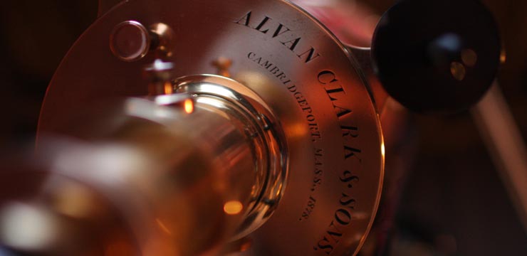
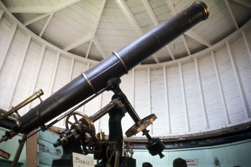
My first logbook entry mentioning the reconstruction of the Drive was back in 2003, over six years ago. During this time I have learned a great deal about the genius of the Clarks, in particular George Basset Clark, whom I believe is responsible for the design of our 8¼-inch telescope’s mount and drive systems. This grand old scope was built in 1878 and I had been thinking about restoring it for some time. So, when the opportunity finally presented itself, I was very anxious to get started.
Initially, there was a big problem to overcome. We did not have the original flyball governor, the heart and soul of the weight drive system. It had been destroyed back in the early seventies. For those of you who are unfamiliar with the story, I will reiterate some of it here, as I believe it to be an important part of the telescope’s history.
Back in the early 1970’s, the flyball governor, right ascension circle and sector drive were removed in an attempt to “improve” the telescope’s tracking ability. The governor and weights were replaced by an electric motor and a “new” Mathis gear was installed on the polar axis. During this time the flyball governor and most of the drive components were brought into the meeting hall and stored in a cabinet. Well, one day vandals broke into the meeting hall and stole the 6-inch Crawford refractor, along with the flyball governor. The governor was subsequently found a few weeks later. It had been smashed on a stone wall. It is truly hard to comprehend how anyone could be so ignorant. Now, I never saw the flyball governor, or any of the supposed pieces after it had been stolen, and I don’t remember who found it out on the stone wall. Anyway, the governor was gone and we had no indication of what it looked like or how it operated other than my feeble recollection of having seen it run the telescope when I was a young lad of 14.
Once I decided to try and replicate this important missing component, it became immediately apparent that much research would be required to track down whatever vital information I could find.
My first step was to simply close my eyes and try to remember what I saw when I was a young boy. I do remember seeing the governor spinning, and with my eyes closed I made an initial guesstimate that it was spinning around 120 RPM, 2 times per second. Well, at least I had somewhere to start.
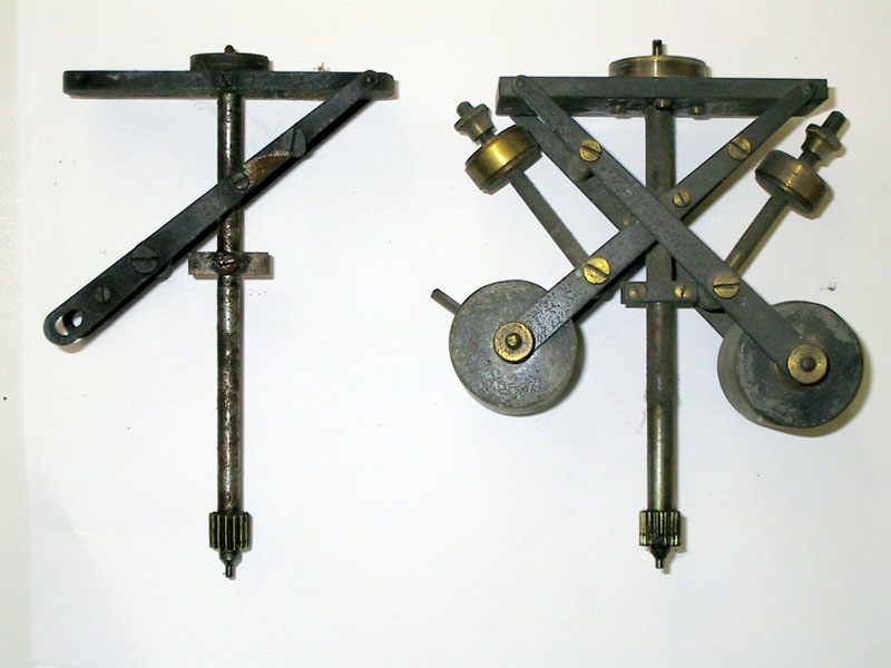
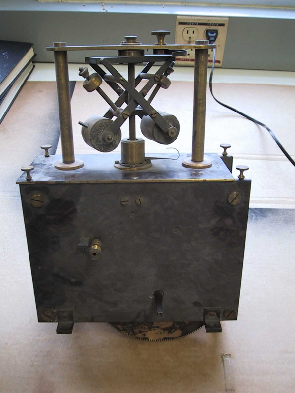
I asked Ed Turco and Bill Penhallow, both long-time Skyscrapers members, to recall what they could about the old drive. Of course I also asked if they had any old pictures. Unfortunately neither had pictures, but Bill recalled that my guesstimate about the speed was probably pretty close, and Ed Turco remembered that there was a hook on the unit that would produce a clicking sound every few seconds; two more vital clues. Next, I contacted John Briggs, renowned Alvan Clark Expert. He had some pictures of an old Fauth governor, which he believed George Clark had based his design upon. This photograph was an important first step in the reproduction effort because we now had a rough idea of the scale of the unit and some insight into its operation. This unit was thought to precede the Clark governor by some short period of time. You can see a copy of this picture below. Notice the little hook that Ed Turco had referred to.
It became apparent after examining this photo that the hook was there to engage a small pin that extended from one of the weights. In this photo the pin is rotated out of position. Look at the left weight to see the pin; it should be facing downward, so that while rotating it could hit the hook after flying out a certain distance. This hook’s function was also immediately apparent as it was there to add friction. When the system of weights flies out too far, the pin engages the hook and this slows the rotation; then as the rotation slows, the weights drop back down slightly and disengage the hook. This was the mechanism by which the speed of rotation was regulated. Ah, another vital piece of information.
I started looking into the physics of these systems and found a great deal of resource material related to the James Watt flyball governor. These governors operate on a principle of centrifugal inertia. As the shaft spins faster and faster, the weights “fly” further out from the axis of rotation. This motion is very well understood and can be described by formulas that were developed for conical pendulums, the details of which I will not bore you with here. Suffice it to say that the angles to which the weight support arms will rise to are directly related to the rotation speed.
Next, I compiled some additional information based on the fact that I had some of the remaining clock drive components that the governor attaches to. In particular, I determined that the idler spur gear which mated to the governor needed to rotate at 1 RPM in order for the telescope to track at the sidereal rate. This figure was arrived at by back tracing the gear train and by counting up the multiple gear ratios.
So, I now knew that the governor was spinning about 120 RPM and the output speed of the governor’s shaft had to be 1 RPM. This indicated an initial estimate of 120 to 1 for the gear reduction box, and knowing this gear ratio allowed me to identify the internal gears; the ones we cannot see inside the box.
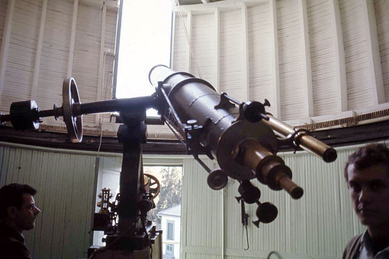
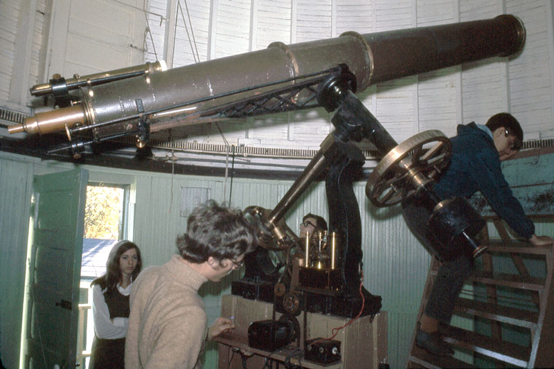
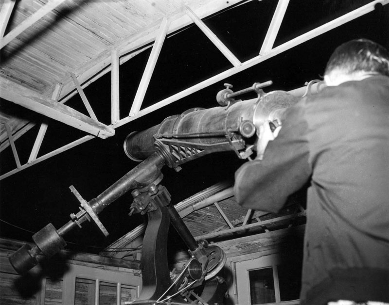
A couple more seasons passed and I was at AstroAssembly 2005 when I noticed that George East was also in attendance. I approached him to see if he might have in his possession any photographs of the old weight drive. As it turns out he did! After several days of looking, he was able to track down several photos from the late 1960’s that showed the flyball governor and how it was situated. Jackpot! I was now able to see what the old governor looked like. More importantly, there were pieces of the drive still on the telescope that were also in these photographs. I was able to measure the parts on the telescope and then measure them again in the photos. These measurements gave me the scale for all of the other dimensions in the photos, and I was able to reproduce all of the required dimensions of the missing components, including the flyball governor.
Once the dimensions were determined I began to back check against some of my previous assumptions. For example, I now knew the length of the flying weights pivot arms, and also the fact that they appeared to be spinning at a 45 degree angle to the vertical axis. This operating angle makes quite a bit of sense because the tangent of 45 degrees is 1, and the tangent of the angle of operation is the coefficient in several of the conical pendulum equations. This simplifies the math because you are now multiplying by 1, a fact that I’m almost certain did not elude George Clark. Now, when I ran the back calculations with the newly acquired length dimensions it turns out that the unit in the 1969 photo was spinning at approximately 150 RPM; not far from my original guesstimate of 120 RPM. So, knowing the RPMs needed to be 150; this set the internal gear ratio to 150 to 1, thereby producing the 1 RPM output speed that I was looking for. It all started to make sense!
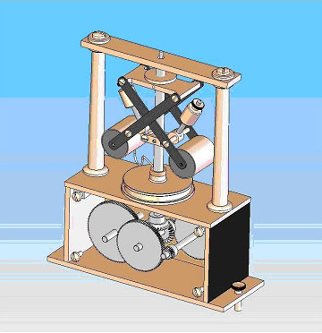
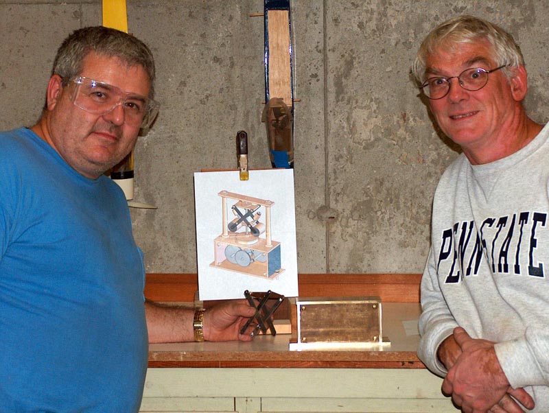
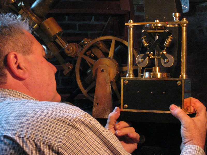
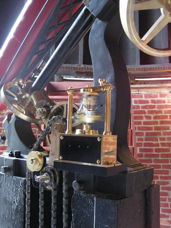
Finally, with the internal gear ratio now identified, and the exterior dimensions known, I was able to design a replica of the governor in SolidWorks. Once the CAD model was completed, it was a simple matter to produce detail drawings of each of the unit’s components.
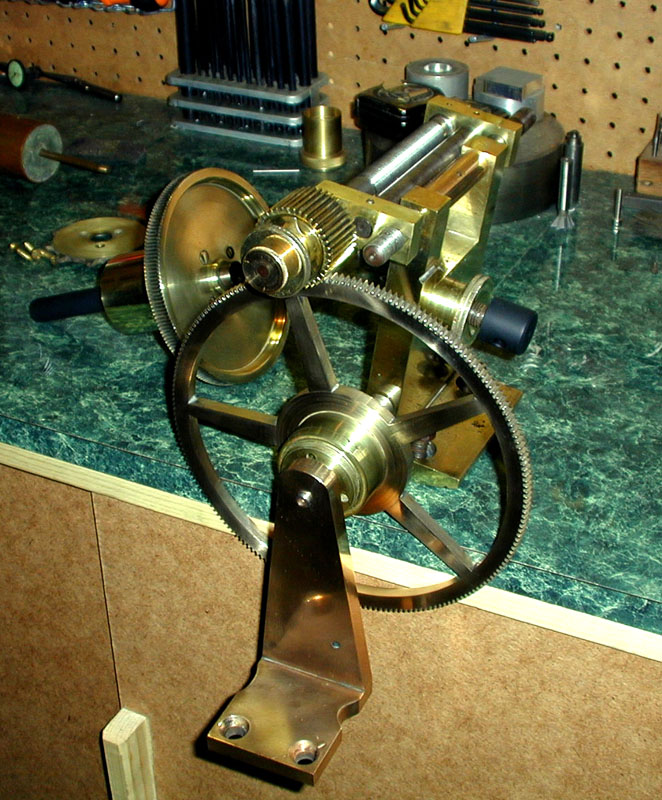
I began fabricating the parts in late fall of 2006. It was at this point that I asked Dick Parker to help me out with some of the machining, as there were many parts to make. Dick has a very fine Moore jig borer, which is the ultimate machine for the job of precision drilling of holes; a definite requirement when placing bearing holes for plate-type clock mechanisms. Dick was more than happy to help, and quite excited as well to be working on such an interesting project.
The governor was virtually completed in the spring of 2007 and Dick and I decided to bring it up to Stellafane that year and enter it into the mechanical competition. We were very fortunate and won a Special Award that year for our work on the governor.
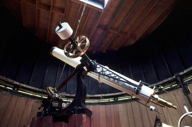
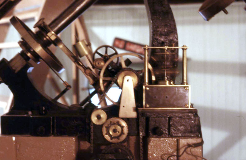
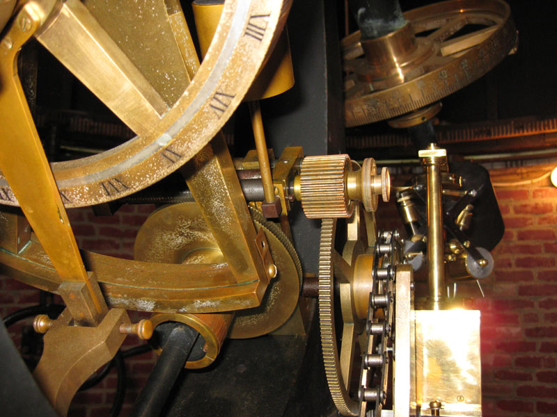
Well, we were almost ready to install the governor back onto the telescope at Seagrave Observatory, but there was still one vital piece of information missing that prevented us from proceeding. I had no idea how the weights and chain system was coupled to the gear train. The photos that George East contributed did not show any details of how the weights were hung. This caused me great mental stress because what I was seeing in these old photos just did not make sense. If you refer to the first photo of the original unit, you will notice that the chain is not wrapped around the ratchet gear in the center of the pier. How did the chain make contact to this component? It was a giant mystery, and if it was not resolved we could not complete the project. I spent several months trying to figure out what was happening with the weight system.
Once again I called on John Briggs to see if he could help me out with the chain mechanism. He did not recall what the old Clark at Seagrave looked like, but he did think that the chain mechanism employed what is known as a Huygens chain, so named after Christiaan Huygens who invented it back in the 1600’s. I began to do a little more research into this chain system. It is also called an endless chain because the whole chain power system forms a continuous loop—really quite ingenious! Anyway, I began to get a feeling for how this chain system worked but was still baffled by what I was seeing in the old photographs. It just did not make any sense that the chain was not connected to the ratchet gear.
Several months passed and I bumped into George East again at a Skyscrapers meeting. I was mentioning to him my problem, and just happened to have a copy of the picture that he had sent to me. I remember saying “boy it sure would have been nice to see what was going on down below the bottom of the photograph.” I had assumed that Frank Seagrave had made some sort of modification to the original system. Immediately George said; “well I wish I had known that sooner. I have some more photos that show those weights, but you didn’t let me know that you were interested in that area.” Doh!
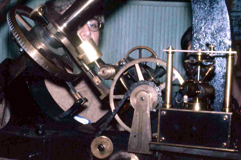
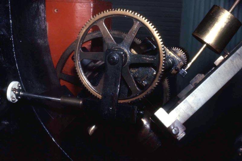
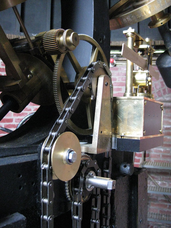
So after another couple of days passed I got the “Ah-ha!” e-mail from George. It contained a picture of the weight winding mechanism that was missing from the previous set of photographs. This new information was vital to the faithful reproduction of the original weight drive system. You can see a copy of this photo above.
Utilizing Photoshop I enlarged the area below the mount and also enhanced the contrast. Ah-ha! It became instantly apparent that Frank Seagrave had replaced the manual winding mechanism with an electric motor, and the chain was simply lowered from the original ratchet sprocket to a new sprocket on the motor shaft. He must have gotten tired of manually winding up the drive. I now knew the last piece of vital information that would allow us to finish the project.
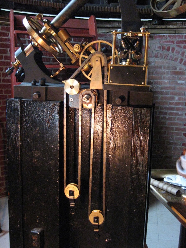
I purchased all of the remaining materials required to complete the project, and began immediately to assemble the last few components. These included the chain and several weights and pulleys. The original ratchet also had to be modified slightly to work with a new, modern chain since the original chain was a late 1800’s style bicycle chain that was no longer available.
After more than six years since its inception, the project was finally finished. The weight drive was test-assembled on the telescope in early April, 2009. During that installation it was noted that a couple of modifications were required to achieve proper operational success. So it was immediately removed and the temporary drive was replaced.
The final installation occurred on July 5th, 2009 and some tweaks were made during the following week. There were a few minor adjustments required on some of the gear mating interfaces and we needed to properly balance the weight loads.
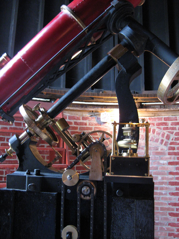
The new “old” drive was re-dedicated and ownership passed to the Skyscrapers Board of Trustees during a ceremony at the annual Skyscrapers Cookout which was held on Saturday, July 11th, 2009. First light with the telescope being driven by its old weight drive occurred on July 13th, 2009 with myself, President Bob Horton and First Vice President Bob Napier in attendance.
The drive worked perfectly. We even managed to adjust out most of the annoying periodic oscillations which had been present as far back as I could remember.
All three of us commented on the apparent spiritual attendance of Frank E. Seagrave, Alvan, Alvan Jr, & George Basset Clark as well.
Regards & Clear Skies All
Related Topics